| A Bahtinov Mask Variant |
Niels Noordhoek produced the Bahtinov Grabber, which uses line recognition algorithms to detect the diffraction spikes produced by the Bahtinov mask. This takes much of the guesswork out of trying to decide if the central spike is really centred.
Grabber analyses the three lines and calculates the displacement between the central line and the intersection of the other two lines.
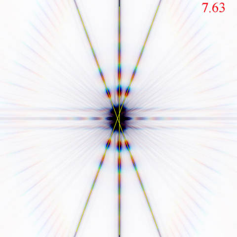
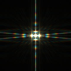
| This example shows a
simulation using another of Niels' software marvels -
Maskulator. The focus error was 300 microns, and the distance between the 'X' intersection and the centre line was 7.63pixels. When approaching the region of 'critical focus' the distance can be less than 1 pixel and so is difficult to measure with high accuracy. |
 |
|||||
| With this in mind, I tried a few different designs that would produce a greater displacement for the same focus error. In theory, if the distance being measured is greater, and there is no loss in accuracy of detecting the lines, then there should be an improvement in accuracy. | ||||||
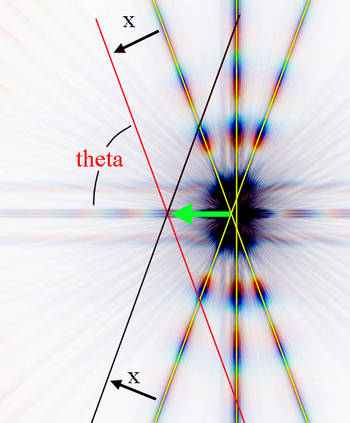
Assume that the angle between the two sloping lines is 2theta, and each line is displaced a distance x. Some simple geometry shows that the intersection point will move a distance x/(sin theta). The distance x is determined by the change in focus position, so to ensure a larger displacement of the intersection point, we must decrease theta. |
 |
|||||
| The standard Bahtinov mask has the angled slits inclined at 40 degrees to each other. Pavel Bahtinov chose this angle because it results in a diffraction pattern that makes it relatively easy to judge by eye if the middle spike is truly central. This results in theta in the above diagram being 70 degrees. (Note that the diffraction spikes are perpendicular to the slits). | 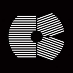 |
 |
||
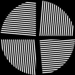
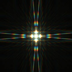
| I constructed this mask, which has the angled spikes inclined at 170 degrees to each other. This makes theta equal to 5 degrees. The resulting diffraction pattern is markedly different. | 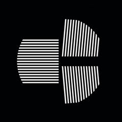 |
 |
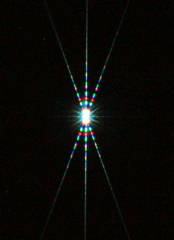
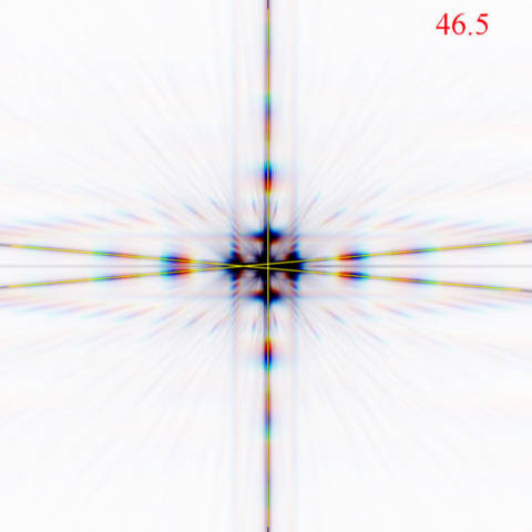
| This
'85 Bahtinov' mask is of no use whatsoever for visual work, because it is now
very difficult to judge when the middle spike is central. However, the Bahtinov
Grabber software has no such problems, and can locate the spikes with sub-pixel
accuracy. With 85 degree angles, mathematics predicts that the displacement between the central spike and the 'X' intersection should be 6.04 times greater than with the traditional Bahtinov mask. In the simulation a shift of 7.63 pixels has been increased to 46.5 pixels. This is a ratio of 6.09 which agrees closely with the maths. The diagram to the right is to the same scale as the first diagram on this page. |
 |
||
| To
test the new mask I made a series of simulations of diffraction patterns using
'Maskulator'. I initially chose a range from -100 microns focus error to +100
microns, with images made every 10 microns. A similar series was made using the traditional design. Niels Noordhoek obligingly rewrote the grabber program so that it could analyse the new mask patterns, and he also made a modification to display the measured focus error to 2 decimal places. |
|||
| Initial results showed that there was indeed an increase in accuracy. The 20 degree mask at 100 microns focus error showed a displacement of 1.99 pixels. The 85 degree mask showed a displacement of 12.68 pixels for the same focus error. This is 6.37 times greater. | |||
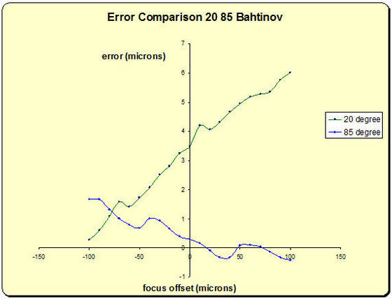
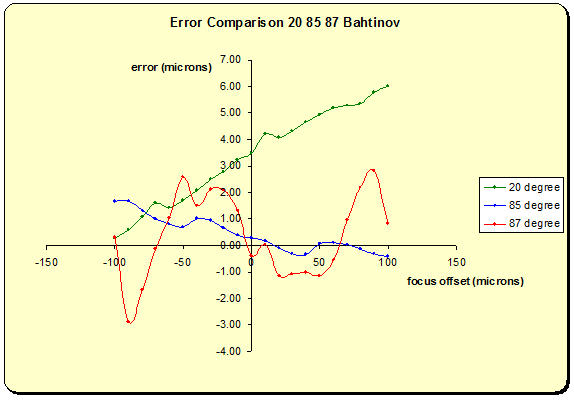
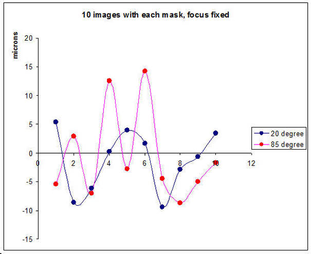
| This graph shows the
difference between the focus error as measured by Grabber, and the generated
focus error in the simulations. As can be seen, the 85 Bahtinov was within 2 microns across the entire range. (The repetitive undulations in the graphs is due to the discrete size of the pixels in the images). |
 |
||
| This animation shows the Bahtinov Grabber
in action as it analyses each
image. |
 |
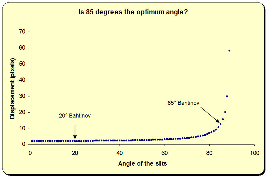
| This graph shows the
displacement between the vertical line and the intersection of the sloping
lines for a diffraction spike shift of 1 pixel. An 89 degree Bahtinov would show a displacement of nearly 60 pixels, but the diffraction spikes would be only 2 degrees apart, and a small error in locating the spike positions would result in a large error in determining the intersection point. It is also likely that Bahtinov Grabber would stand more chance of getting confused if the lines were that close together. |
 |
|
An experimental 87 degree mask showed errors of over 2 microns over the -100 to +100 micron range. The worst error with the 85 degree mask was 1.66 microns. It is likely that 85 degrees is close to the optimum value. |
 |
Preliminary conclusions are that the 85 degree variant of the Bahtinov mask will provide greater accuracy than the 40 degree mask when used in conjunction with software such as the 'Bahtinov Grabber'. |
|
See this
YouTube video which shows how
the diffraction spikes move for the 85 degree mask. which shows how
the diffraction spikes move for the 85 degree mask.Note that when purely visual inspection is used to determine optimum focus, then the traditional Bahtinov should be used, or another mask design, the Carey Mask. |
|
Star tests (15th May 2010) |
|
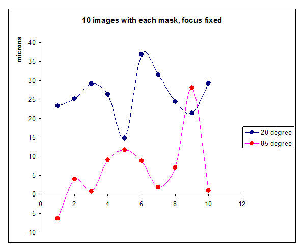
| Initial tests on the sky show that
the 85 degree Bahtinov works in principle, but the error in precisely locating
the diffraction spikes is significantly greater than with the 20 degree mask.
This was tested by fixing the telescope focus and then taking 10 exposures with
each type of mask. The 20 degree mask gave values of defocus of 23.23, 25.10, 29.13, 26.29, 14.73, 36.88, 31.52, 24.43, 21.39, 29.17 microns The 85 degree mask gave -6.42, 4.00, 0.70, 9.98, 11.67, 8.82, 1.77, 7.03, 28.12, 0.88 microns |
| The
spread of values for the 85 degree mask was broader than for the 20 degree
mask. Although both masks will allow critical focus to be reached it was
disappointing that the 85 degree mask did not live up to
expectations. |
 |
|||
| 21 May Another test. Fixed focus. Quite close agreement between the two masks this time, but still greater spread with the 85 degree mask. |
 |
|||
 |
|
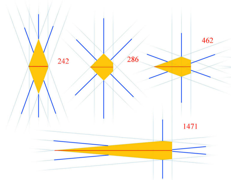
| The diagram above illustrates
the problem. Examples are for 20, 45, 70 and 85 degree masks. Dark blue lines
represent the diffraction spikes. Paler lines show the error uncertainty in
measuring the true line positions. Assuming that the error in finding the
intersection of the sloping lines lies to the left, then the orange shaded
areas show all possible positions that the measurement could give. The numbers
given show relative values. Clearly the 85 degree mask could have a maximum
error 6.07 times greater than the 20 degree mask, neatly cancelling out any
advantage! If time permits, I will try 45 and 70 degree masks. Regrettably the hoped for increase in sensitivity of 6 has not been realised. |
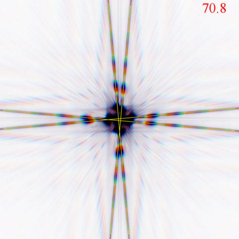
| Yet another mask
design... It is possible to get even greater displacements between diffraction spikes. This variant has two pairs of spikes. The intersections of the spikes move perpendicular to each other. The slits are arranged so as to generate lines that move in directions that will produce the maximum displacement. |
 |
 |
|
| In this simulated image the one intersection has moved to the left, the other downwards. This example is also for a defocus of 300 microns. Line detection software that measured the distance between the two intersections would find a 70.8 pixel displacement (compare with 46.5 and 7.63 for the 85 and 20 degree Bahtinovs). See this YouTube video
|
 |
||